
HUBS & BRAKES ADJUSTMENT, DISMANTLING AND RE-ASSEMBLY
Front & Rear Hub and brake - A Group Models before Engine No. ZA7-101
Both wheels are of the quickly, detachable type and are interchangeable.
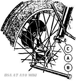
Fig. A31
Front Wheel Removal and Replacement
Slacken the pinch bolt A. Fig. A31. at the front of the nearside fork end. insert tommy bar in the hole in the spindle end B and unscrew. Note that the spindle has a left hand thread, and therefore unscrews clockwise. The spindle can then be pulled right out, and the wheel should be pulled sideways toward the nearside of the machine, so as to disengage the coupling splines on the hub from the brake. As this is done. the distance bush C will slide into the fork end. The wheel can now be dropped out.
To replace the wheel the above operations are carried out in the reverse order. The action of tightening the wheel spindle restores the bush C to its correct position. Do not forget finally to tighten the pinch bolt A.
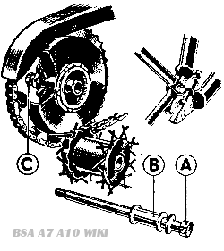
Fig. A32
Rear Wheel Removal and Replacement
The rear wheel is removed in a somewhat similar manner. The spindle A, Fig. A32, has a right hand thread and therefore unscrews in an anti-clockwise direction. The distance bush B falls clear of the machine when the spindle is removed, or alternatively the spindle can be pulled out until it is clear of the hub and then slid backwards out of the slotted chainstay end, carrying the bush with it.
This is the most convenient way of dealing with the bush when refitting the wheel. When detaching the rear wheel, it is quite unnecessary to touch the hexagon nut C on the nearside.
Dismantling and Re-assembly of the Hubs
The hubs are fitted with two ballraces which are a light press fit on the hollow spindle and in the hub shell. Remove the dust cap A, Fig. A33 and felt washer B. Unscrew the ballrace retaining ring C. This ring has a left hand thread and therefore unscrews in a clockwise direction.
With the aid of a suitable soft drift applied to the end of the hollow spindle D, drive out the spindle and ballrace E. As the spindle comes away the distance bush F will be released. The only parts remaining in the hub are the ballrace G and the shim H, and these need not be disturbed unless the ballrace is suspected of being faulty. Wash it thoroughly in paraffin to remove all trace of grease when any play will be immediately detected. If it is decided to replace the race it can be driven from the hub shell with the aid of a soft drift.
Removal and Dismantling of the Front Brake Drum
Fig. A33. Section through the front hub.
After removal of the wheel the brake drum is held in position in the frame by means of a stud which passes through a lug on the fork leg. With the nut removed the complete drum can be withdrawn.
The brake drum cover plate can be withdrawn from the brake drum after removal of the spring circlip J, Fig. A33. The plate will be seen to carry the brake shoes together with their fulcrum pin and operating arm and a thrust race with its accompanying washers. Note that the smaller diameter washer goes next to the cover plate.
It is unlikely that the brake shoes, fulcrum pin and operating arm will require attention, although the latter should be checked for freedom of movement and greased if necessary.
To remove the brake shoes, lay the drum cover plate flat on a bench (shoes upper most) and lever the shoes upwards. They can then be drawn over and free of the cam and fulcrum pin. To replace, attach the springs and reverse the method of removal. If the cam pads show excessive wear, new shoes should be fitted. If only the brake linings are worn, these alone need be replaced.
If examination of the brake drum shows that the splines have become worn and the braking surface scored, a new drum must be fitted. The drum must not be machined to produce a new braking surface. To do so is only a temporary cure and further attention would be required later.
When new linings or new shoes have been fitted, the brakes must be centralised after refitting the wheel. To do this. replace the brake cover plate, complete with shoes, fulcrum pin and cam. in the brake drum. Slacken the fulcrum pin nut, and turn the cam so as to open the brake shoes in the normal manner. The fulcrum pin will then move in its slot until both shoes are pressing equally on to the drum. Tighten the fulcrum pin nut firmly and release the brake.
Removal and Dismantling of the Rear Brake Drum.
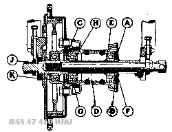
Fig A34. Section through the rear hub.
After removal of the rear wheel the brake, drum is held in position in the wheel by nut J. Fig. A34. To remove the drum disconnect the chain and rear brake rod, slacken nut J, move the drum towards the offside of the machine until the lug on the frame disengages from the slot in the brake anchor plate, and then slide the drum to the rear, until it is clear of the chainstay ends.
With the brake drum removed from the frame, the brake drum cover plate, to which are attached the brake shoes, can be withdrawn, together with their fulcrum pin and operating arm. It will be seen that these are similar in construction to those of the front brake, and the instructions given for the front brake will apply.
The hub ballrace, which is totally enclosed in the brake drum, should not normally require attention. If it has been decided to replace this race, however, its housing can be removed from the brake drum by unscrewing the nuts and withdrawing the bolts that pass through the splined ring, the brake drum and the ballrace housing. Note that the nuts are locked in position by three locking strips: it is essential that these are fitted on re-assembly.
The brake drum ballrace is held in position in its housing by means of a spring circlip K. which can be removed with the aid of a screwdriver. The replacement ballrace should be well greased before fitting the washer in place to prevent grease entering the brake drum. When replacing the bearing housing in the drum, make sure that its face is clean and free from burrs, as failure to do this may result in the brake drum running out of truth.
Brake Adjustment
The front brake is adjusted by means of the screwed sleeve on the cable stop. fitted to the brake cover plate.
the rear brake is adjusted by means of a knurled nut on the end of the brake rod.
Front Hub and Brake (7 In. Brake) - A, B and M Group Models
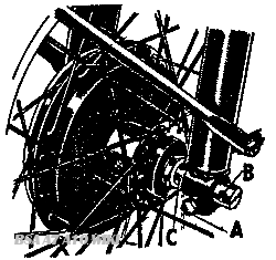
Fig. A31 (a). Wheel Removal
Wheel Removal and Replacement
To remove the front wheel, first disconnect the brake cable, then slacken the pinch bolt A (Fig. A31 (a)). Insert a tommy bar in the hole in the head of the spindle at B and unscrew the spindle, noting that it has a left hand thread and therefore unscrews in a clockwise direction. With the spindle withdrawn the bush C should be pulled out to its fullest extent. This will leave the wheel free to be pulled away from the right hand fork leg and withdrawn from the machine.The wheel is replaced in the reverse order, noting that the brake plate stop must be located in its recess at the rear of the right hand fork leg. It is most important that after the spindle has been tightened and before the pinch bolt is tightened, the forks are depressed once or twice to enable the left hand fork end to position itself on the distance bush. If this precaution is not observed, the fork leg may be clipped out of position and will not function correctly.
Dismantling and Re-assembly of the Hub
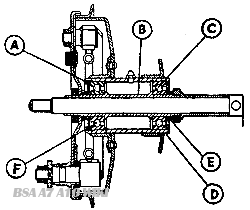
Fig. A32(a). Section of Front Hub (7 in. Brake)
This is fitted with ball journal bearings and therefore no adjustment is necessary or provided for. The only attention required is periodical grease gun lubrication.
If it becomes necessary to replace the bearings unscrew the nut retaining the brake anchor plate and remove the plate together with the brake mechanism.
Unscrew the cap A (Fig. 32(a)) noting that this has a left hand thread and therefore unscrews in a clockwise direction. Using a hide mallet from the brake drum side, drive out the hollow spindle B which will carry with it the nearside ballrace C, dust Cap D, and distance piece E.
Only the offside ballrace F now remains in the hub and this should be driven out with the aid of a soft drift.
During re-assembly ensure that the ballrace F is fully home and that the retaining collar A is quite tight.
Brake Relining
To remove the brake shoes lay the drum cover plate flat on a bench and lever the shoes upwards. They can then be drawn over, and free of the cam and fulcrum pin. If the cam pads show excessive wear the brake shoes should be renewed.
When new linings or new shoes have been fitted, the brakes must be centralised after refitting the wheel. To do this, replace the brake cover plate, complete with shoes, fulcrum pin and cam in the brake drum. Slacken the fulcrum pin nut. and turn the cam so as to open the brake shoes in the normal manner. The fulcrum pin will then move in its slot until both shoes are pressing equally on to the drum. Tighten the fulcrum pin nut firmly and release the brake.
Front Hub and Brake (8 in. Brake)
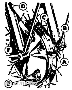
Fig. A31 (b). Wheel Removal
Wheel Removal and Replacement
To detach the wheel, first disconnect the brake cable by pushing it out of the brake clip at E and unscrewing it from the bracket at F. Remove the torque arm nut C and undo the pinch bolt A. Insert a tommy bar in the hole in the head of the spindle at B and unscrew the spindle, noting that it has a left hand thread and therefore unscrews in a clockwise direction. Support the wheel as the spindle is withdrawn, and when it is dear the wheel can be pulled away from the right hand fork leg and removed from the machine.
After removal do not let the wheel fall on to the bush which projects from the brake drum side of the hub. Although the bush is pressed in, it may, if subjected to a sharp blow, be forced back into the hub. If this should happen the bush can be retrieved and re-positioned with the aid of the wheel spindle.
The wheel is replaced in the reverse order to that for removal. It is most important that after the spindle has been tightened and before the pinch bolt is tightened, the forks are depressed once or twice to enable the left hand fork end to position itself on the spindle shank. If this precaution is not observed, the fork leg may be clipped out of position and will not function correctly.
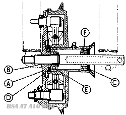
Fig. A32(b). Section of Front Hub (8 in. Brake)
Dismantling and Reassembly of the Hub
Withdraw the brake plate which is a push fit on the bush B (Fig. A32(b)). Remove the locking split pins and unscrew the bearing retaining collars C and D which have normal right hand threads. Replace the spindle and drive out the brake side ball race E together with the bush B by striking the end of the spindle with a hide mallet. Only the ball race F now remains in the hub and can be removed with a suitable soft drift.
Before replacing the bearing retaining collars ensure that the rubber oil seals in them are in good condition. The collars should be done up quite tight and if necessary fresh holes should be made for the locking split pins.
Brake Relining
To remove the brake shoes lay the drum cover plate flat on a bench and lever the shoes upwards. They can then be drawn over, and free of the cam and fulcrum pin. If the cam pads show excessive wear the brake shoes should be renewed.
Rear Hub and Brake - A, B and M Group Models (With Plunger Type Rear Suspension)
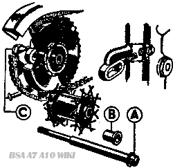
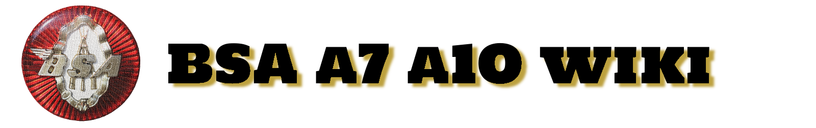
Fig. A31(c) Rear Wheel Removal (Spring Frame)
Rear Wheel Removal and Replacement
Remove the smaller outer nut C (Fig. A.31(c)) on the left hand side of the rear wheel spindle, and withdraw the spindle A, from the right hand side of the machine.
The distance bash B will normally fall clear when the spindle is removed. The wheel should then be pulled towards the right hand side of the machine until it is free from the spline engaging it with the brake drum. When the hub is free from the drum the wheel can be dropped out. To replace the wheel the operations are carried out in the reverse order. When detaching the rear wheel, it is quite unnecessary to touch the larger of the two hexagonal nuts on the left hand side of the spindle.
Dismantling and Re-assembly of the Rear Hub
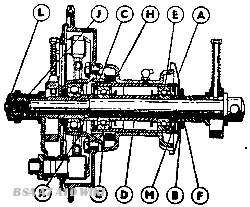
Fig. A32(c). Section through the Rear Hub
The hub is fitted with two ballraces which are a light press fit in the hub shell Remove the dust cap A (Fig. 32(c)). Unscrew and remove the two screwed rings C and M. These rings are left hand threaded, and therefore unscrew clockwise. Remove distance piece F.
Place the wheel spindle through the hub from the offside. Using a hide mallet tap the head of the spindle so as to drive the offside ballrace toward the centre of the hub shell. By this means the brake drum side race wfll be driven out, after which the distance pieces D and H can be removed.
The only part now remaining in the shell will be the offside ballrace which can be driven out with a soft drift.
Removal and Dismantling of the Brake Drum
After removal of the rear wheel the brake drum is held in position in the wheel by nut L (see Fig. A32(c)). To remove the drum disconnect the chain and rear brake rod, remove nut J and withdraw the drum.
With the brake drum removed from the frame, the brake drum cover plate, to which are attached the brake shoes, can be withdrawn, together with their fulcrum pin and operating arm.
The brake drum ballrace is held in position in its housing by means of a spring circlip K, which can be removed with the aid of a screwdriver. The replacement ballrace should be well greased before fitting the washer in place to prevent grease entering the brake drum.
If examination of the brake drum shows that the teeth have become worn and the braking surface scored, a new drum must be fitted. The drum must not be machined to produce a new braking surface. To do so is only a temporary cure and further attention would be required later. The spline bolted to the brake drum should be replaced if there is any play between it and the spline on the wheel hub.
Brake Relining
To remove the brake shoes lay the drum cover plate flat on a bench, and lever the shoes upwards. They can then be drawn over, and free of the cam and fulcrum pin. If the cam pads show excessive wear the brake shoes should be renewed. When the brake shoes are removed the linings can be replaced as described
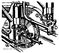
Fig. A33(c). Rear Chain Adjustment
Rear Chain Adjustment
Put the machine on its stand. The rear wheel must be at its lowest point in the suspension unit when the adjustment is made. Undo nut A (Fig. A33(c)) several turns and slacken nut B just sufficiently to allow the wheel to move.
Screw in the adjusters D to tighten the chain. There should be a total up and down movement of half an inch at the centre of the chain span. See that the wheel spindle is up against the adjusters and that the wheels are in line. Check the alignment by means of a taut piece of string, which should be equidistant from the front and rear of each wheel.
Tighten the large hexagon nut B very firmly. followed by the smaller nut A. Readjust the rear brake.