THE TELESCOPIC FORKS
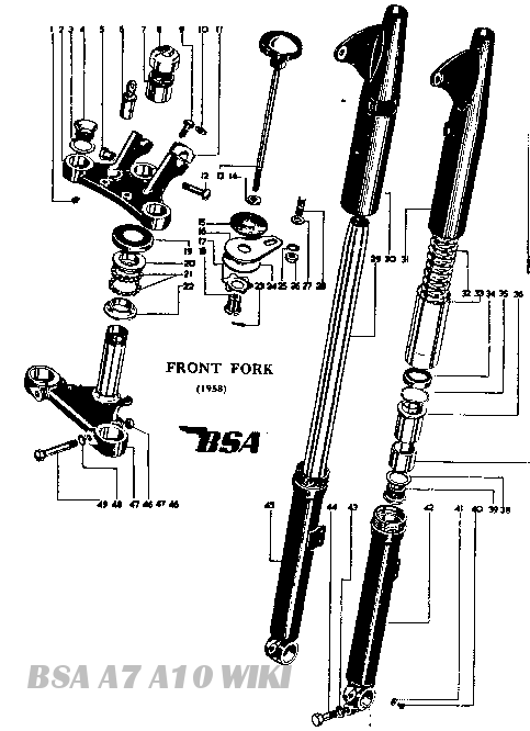

B.S.A. hydraulically damped telescopic forks are entirely automatic and no adjustment is necessary or provided for. The only maintenance required is occasional topping up with oil, the necessity for which will be indicated by excessive up and down oscillation.
Each leg should contain a quarter of a pint (142c.c.). or three-eighths of a pint (213c.c.) for models fitted with the larger top bush in the sliding tube. The correct grade of oil to use is S.A.E. 20 for all models.
To check the oil level within the forks, place the machine on its stand, remove the plated hexagon cap from the top of each shaft and pass a thin rod down inside to act as a dipstick. The depth of oil should be approximately seven and seven-eighth inches (quarter pint), or nine and one-sixteenth inches (three-eighths pints).
Later models have a drain plug fitted at the base of each fork leg. It is, therefore, only necessary to drain the oil and refill with the correct quantity.
QUARTER-PINT CAPACITYModels C10, C10L (1956 onwards), C11, C11G. C12, B31/33 (up to 1956). B32/34 and Gold Stars (up to 1952). M20. M21. M33, "A" Group (up to 1952).
THREE-EIGHTHS PINT CAPACITY.Models B31/33 (1956 onwards). B32/34 and Gold Stars (1952 onwards). "A" Group (1952 onwards)
Dismantling

Fig. X3a
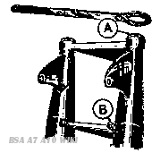
Fig. X2a
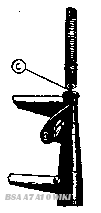
Fig. X2b
The most convenient way to dismantle the forks is to remove each leg separately, having first detached the front wheel and mudguard. Remove the filling plug at the top of the leg (A, Fig. X2a) and then slacken on the pinch bolt B on the bottom yoke
Insert a screwed plug, B.S.A. Service Tool No. 61-3350, into the thread at the top of the leg which is exposed when the filling plug is removed (C.Fig. X2b).and tap this vigorously with a suitable hammer or mallet, whereupon the leg should be released and can be withdrawn downwards from the yokes.
Having withdrawn the leg it should be held in a vice by the lug at the bottom through which the wheel spindle normally goes, and the spring should then be lifted off. The lower spring seating is slotted to accommodate a special unscrewing tool, B.S.A. Service Tool No. 61-3005. consisting of a tubular member with suitable dogs to engage in the slots, and with this the spring seating, together with the tubular sleeve which normally encloses the lower part of the spring, can be unscrewed (D. Fig. X3a).
Having drawn the tubular sleeve clear as far as possible, being careful to avoid drawing the oil seal up the taper of the leg, a circlip holding the upper sliding bush in position, will be revealed, and this should then be prised out (E. Fig. X3b).
NOTE: During assembly one turn of No. 5 Twine round the undercut will provide an additional and effective seal. Overlap the ends and trim off.
Next pull out the main tubular member which will come away complete with the circlip the two bashes and the oil seal housing. The presence of oil in the lower part of the assembly may offer some slight obstruction to the withdrawal of the main tube. especially if the oil is cold and thick, but this can easily be poured out. To remove the bushes and oil seal housing, unscrew the gland nut at the lower end of the main tube (F. Fig. X4a). As the operation necessitates clamping the main tube. care should be taken to ensure it is not damaged. It is recommended it be secured approximately five to seven inches from its upper end.
To remove the oil seal from its housing B.S.A. Service Tool No. 61-3006 should be used G, and to replace it use Tool No. 61-3007 H.
Take care to fit the internal rubber sleeve facing downwards K.
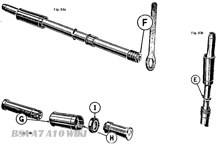
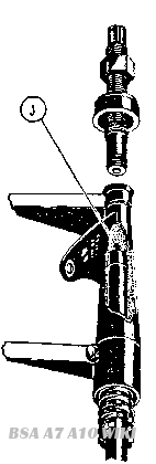
Fig. X4
Re-assembly
Re-assembly is carried out in the reverse order to dismantling. All the components should be quite clean. Remove any road grit from the springs and then smear them liberally with thick grease before assembly. Ensure that the oil seal is not damaged or worn. To fit the main fork
tubes screw B.S.A. Service Tool (61-3350) into the top of the tube (J. Fig. X4) and pull it up sharply into the top yoke. Then fit the collar and nut on to the tool and draw the tube fully home into the yoke. When the tube is quite home then the pinch bolts on the lower yoke should be tightened, the tool may then be removed and after filling the legs with the correct amount of oil the top plugs should be replaced and fully tightened.
To remove the two yokes and the steering stem from the frame, it is necessary first to slacken off the pinch bolt at the rear of the top yoke. Withdraw (he split pin under the head of the steering damper knob, screw off the knob, then the top nut immediately under it. The steering damper mechanism can (hen be withdrawn downwards from the steering stem and the steering head bearing adjusting sleeve should be unscrewed by means of B.S.A. Service Tool No 61-3002 or 61-3008 for A Group models. The steering stem complete with bottom yoke, can then be withdrawn from underneath.

