
ENGINE ADJUSTMENTS WHICH CAN BE DONE WITHOUT DISMANTLING
Oil Pressure Release Valve
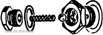
Fig. A3. The Pressure Release Valve (exploded view)
This valve (Fig. A3) is interposed between the delivery side of the pump and the Big End bearings. It is preset to control the pressure in the supply system and it should be examined periodically when changing the oil to ensure that it is operating freely and not impeded by the presence of even tiny particles of foreign matter. If the ball is prevented from seating properly there is a danger of oil starvation at the big ends.
After dismantling all parts of the valve should be thoroughly rinsed in petrol and allowed to dry before re-assembly. Note that both hexagons must be screwed right home and made really tight.
Valve Clearances
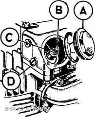
Fig. A4. Tappet adjustment
Valve clearance checking or adjustment should only be carried out when the engine is quite cold. Remove the sparking plugs, and the rocker inspection covers A, (Figs. A4 or A4a). On the early models with separate rocker boxes, illustrated in Fig. A4, it is also necessary to remove the small plugs D. to permit insertion of the feeler gauges and a special tool from the tool kit will assist in removing the caps A.
On A10 and Swinging Arm models the petrol tank should be removed to provide access to the rocker box covers. Do not forget to disconnect the fuel pipes and the strap beneath the tank, connecting the two halves.
The cams are of special design. Because of this it is essential that when checking or adjusting the clearance of any valve it should be closed, with its tappet on the base circle, or neutral portion of the cam. To obtain this position for the drive-side inlet valve turn the engine until the gear-side inlet valve is fully open. Similarly, to set the gear-side inlet valve in the correct position, turn the engine until the drive-side inlet valve is fully open. Follow the same procedure exactly for the two exhaust valves.
Having turned the engine until the valve under consideration is in its correct position, insert a feeler gauge between the adjusting pin B and the valve stem or valve end cap
The clearances should be as follows:
|
Engine |
Inlet |
Exhaust |
|
All A7 Engines up to Engine No. XA7.601 |
.003 in |
.003 in |
|
All A7 Engines from Engine No. XA7.601 to ZA7.11192 |
.015 in. |
.015 in. |
|
A10 Engines and A7 Engines after Engine No. AA7.101 |
.010 in. |
.016 in. |
|
A10 Super Flash, |
.008 in. |
.008 in |
|
A7 Shooting Star |
.008 in. |
.012 in |
|
A10 Road Rocket |
.008 in. |
.008 in |
|
A10 and A10 S/R with frame prefixed "GA" |
.008 in. |
.010 in |
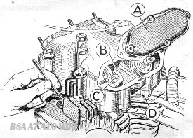
Fig.A4a Valve clearance adjustment and ignition setting
To adjust the clearance; if it is found to be incorrect, hold the pin with one of the tappet spanners and with the other tappet spanner release the locknut C . Then, holding nut C , screw pip B up or down as required, until the correct amount of play is obtained.
Hold the arm B with its spanner and tighten nut C very securely. When C is properly tight check the play again to make certain that it has not been altered while tightening up the nut. Check and adjust all four adjusters in the same manner, and do not forget that this must be done when the engine is quite cold. Finally, replace the rocker box covers, the caps D , and the sparking plugs.
Clearances tend to increase slightly when the engine warms up to its working temperature, and if an attempt is made to adjust clearances 'while the engine is warm there may be insufficient clearance when the engine is cold. Running an engine without enough tappet clearance is harmful to the valve seats, and one of the commonest sources of trouble in this direction.
Ignition Timing
It is a rare occurrence for the magneto pinion to slacken off and disturb the ignition setting, and it is not advisable to interfere with the standard setting unless it is known to be at fault.
Before checking the timing it is advisable to check and if necessary adjust the contact breaker points, as a slight variation of the points tends to advance or retard the timing (opening the points advances the timing, closing them retards timing). The fully opened gap at the points should be .010 in.—.012 in. To check the timing remove the rocker box caps and the sparking plug from the gear-side cylinder.
Turn the engine forward until the gear-side piston is at the top of its compression stroke. This can be checked by means of a rod inserted through the sparking plug hole and resting on the piston head. If, when the piston is in this position, either of the valves is found to be partly open, this means that the piston is at the top of the wrong stroke, and the engine must accordingly be turned through one complete revolution. If tappet clearance can be felt at both valves (see Tappet Adjustment) the piston will be at its correct top dead. centre for ignition timing.
A7 Standard 5/16 in. before T.D.C. fully advanced
A7 Star Twin, A7 Shooting Star 3/8 in. before T.D.C. fully advanced
A10 Golden Flash 11/32 in. before T.D.C. fully advanced
A10 Super Flash, A10 Road Rocket 3/8 in. before T.D.C. fully advanced
A10 and A10 S/R with frame No. prefixed "G.A" 13/32. B.T.D.C.
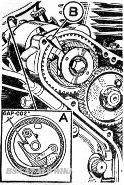
Fig.5. Automatic advance and contact breaker mechanism
Having satisfied yourself that the piston is at the correct top dead centre, turn the engine back until the piston has descended by the amount shown in the above table.
Leaving the engine set in this position, turn the contact breaker in its normal direction of rotation, until it is in the fully advanced position, the points should just be beginning to open, by not more than .002 in. on the bottom contact breaker cam. (A. Fig. A5.)
If the timing requires resetting remove the timing cover and unscrew the bolt locking the magneto pinion and automatic advance mechanism on its shaft. Note that the pinion is self-extracting, if the nut is unscrewed the pinion will be drawn from it's taper.
Leaving the engine set at the position described for checking the ignition, turn the contact breaker in its normal direction of rotation, i.e. clockwise, until the points are just beginning to open. by the action of the arm on the bottom cam.
Wedge the automatic advance mechanism in the advanced position as shown at B, Fig. A5, and holding the contact breaker in position tighten the magneto pinion bolt. Finally re-check the ignition setting.
It cannot be too strongly emphasised that the ignition timing must be correctly set for satisfactory engine performance, and also that any temptation to improve upon the maker's settings should be avoided, as this setting has been found best after careful trial and experiments. The fact that this engine is fitted with automatic Ignition advance makes it all the more necessary that the above timing instructions should be faithfully carried out.