

CARBURATION.
Monobloc and Separate Float Chamber Type – All models
How the Carburettor Works
The function of the carburettor is to atomise the petrol and proportion it correctly with the air drawn in through the intake on the induction stroke. The action of the float and needle in the float chamber maintains the level of fuel at the needle jet, and when the engine is stopped and no further fuel is being used the needle valve cuts off the supply.
The twist grip controls, by means of a cable, the position of the throttle slide and the throttle needle and so governs the volume of mixture supplied to the engine.
The mixture is correct at all throttle openings, if the carburettor is correctly tuned.
The opening of the throttle brings first into action the mixture supply from the pilot jet, then as it progressively opens, via the pilot by-pass the mixture is augmented from the needle jet. Up to three-quarter throttle this action is controlled by the tapered needle in the needle jet. and from three-quarters onwards the mixture is controlled by the main jet.
The pilot jet J, which in the older type of carburettor is embodied in the jet block, has been replaced in the Monobloc carburettor by a detachable jet (9) (Fig. X5) assembled in the carburettor body and sealed by a cover nut.
The main jet does not spray directly into the mixing chamber, but discharges through the needle jet into the primary air chamber and goes from there as a rich petrol/air mixture through the primary air choke into the main air choke.
Although the maintenance and tuning instruction contained in this Service Sheet apply equally well to the Monobloc and separate float chamber types of carburettor, the new instrument has been designed with a view to giving improved performance, and certain constructional changes have been made,
The float chamber is a drum-shaped reservoir, die cast in one piece with the mixing chamber. The material used being zinc-alloy. The float is designed to pivot instead of rising and falling, as in the separate float chamber type, and as it does so, it impinges on a nylon needle controlling the inflow of fuel.
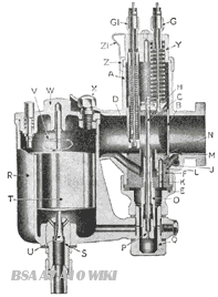
|
A.
|
Mixing Chamber |
O.
|
Needle jet |
|
B.
|
Throttle Valve |
P.
|
Main Jet |
|
C.
|
Jet Needle - and Clip above |
Q.
|
Float Chamber Holding Bolt |
|
D.
|
Air Valve. |
R.
|
Float Chamber |
|
E.
|
Mixing Chamber Union Nut. |
S.
|
Needle Valve Seating |
|
F.
|
Jet Block. |
T.
|
Float. |
|
G.
|
Cable Adjuster |
U.
|
Float Needle Valve. |
|
GI.
|
Cable Adjuster |
V.
|
Float Needle Clip |
|
H.
|
Jet Block Barrel |
W.
|
Float Chamber Cover. |
|
J.
|
Pilot Jet. |
W1.
|
Tickler. |
|
K.
|
Passage to Pilot. |
X.
|
Float Chamber Lock Screw. |
|
L.
|
Pilot Air Passage |
Y.
|
Mixing chamber Top Cap. |
|
M.
|
Pilot Mixture Outlet |
Z.
|
Mixing Chamber Lock Ring |
|
N.
|
Pilot By-pass. |
Z1.
|
Mixing chamber security spring. |
Variations of up to 20° in the angle of the carburettor when fitted, do not affect the working of the float, therefore it lends itself to use for down draught carburation and is not so greatly effected by the degree of lean when cornering. Access to the float (Fig. X6) is gained by removing a plate held in place by three screws.
Compensation for over-rich mixture which results from snap throttle openings, is provided by bleed holes in the needle jet (Fig. X5). A compensatory air bleed is provided, this is the larger of the two holes at the mouth of the air intake, which leads to the space around the needle jet. (Fig. X5).
The pilot intake is the smaller of the two holes, and operates in conjunction with the detachable pilot jet (Fig. X5). This pilot mixture is adjusted as before, by an adjusting screw. (Fig. 8a.)
Hints and Tips. Starting from Cold
Flood the carburettor by depressing the tickler and close the air control, set the ignition. say. half retarded. Then open the throttle about 1/8", then kick start If the throttle is too far open, starting will be difficult.
Starting. Engine Hot
Do not flood the carburettor, but it may be found necessary with some engines to close the air lever, set the ignition to half-retarded, the throttle to 1/8" open and kick-start If the carburettor has been flooded and won't start because the mixture is too rich—open the throttle wide and give the engine several turns to clear the richness, then start again with the throttle 1/8" open, and air valve wide open. Generally speaking it is not advisable to flood at all when an engine is hot.
Starting General
By experiment, find out if and when it is necessary to flood, also note the best position for the air lever and the throttle for the easiest starting. Excessive flooding, particularly when the engine is hot, will make starting more difficult. It is necessary only to raise the level of petrol in the float chamber, by depressing the tickler.
Sectional Illustrations of Carburettors. Types 375, 376 and 389
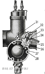
Fig. X6 - Sectlon through float chamber
|
1
|
Mixing chamber top |
18
|
Mixing chamber cap spring |
|
2
|
Mixing chamber cap |
19
|
Cable adjuster (air) |
|
3
|
Carburettor body |
20
|
Cable adjuster (throttle) |
|
4
|
Jet needle clip |
21
|
Tickler |
|
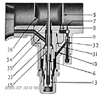
5
|
Throttle valve |
22
|
Banjo bolt |
|
6
|
Jet needle |
23
|
Banjo |
|
7
|
Pilot outlet |
24
|
Filter gauze |
|
8
|
Pilot by-pass |
25
|
Needle seating |
|
9
|
Pilot jet |
26
|
Needle |
|
10
|
Petrol feed to pilot jet |
27
|
Float |
|
11
|
Pilot jet cover nut |
28
|
Side cover screws |
|
12
|
Main jet cover |
29
|
Air to pilot jet |
|
13
|
Main jet |
30
|
Feed holes to pilot jet |
|
14
|
Jet holder |
31
|
Bleed holes in needle jet |
|
15
|
Needle jet |
32
|
Primary air choke |
|
16
|
Jet block |
33
|
Primary air passage |
|
17
|
Air valve |
34
|
Throttle valve cut away |
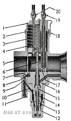
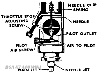
Fig. X7 Section through mixing chamber, showing air valve and throttle closed
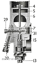
Fig. X8 Set the throttle adjusting screw (30) to hold the throttle open sufficiently to keep the engine running when the twist grip is shut off.The pilot air adjusting screw (29) regulates the strength of the mixture for idling and for the initial opening of the throttle. The screw controls the depression on the pilot jet by metering the amount of air that mixes with the petrol.
STARTING. SINGLE LEVER CARBURETTORS. OPEN THE THROTTLE VERY SLIGHTLY FROM THE IDLING POSITION AND FLOOD THE CARBURETTOR MORE OR LESS ACCORDING TO THE ENGINE BEING COLD OR HOT RESPECTIVELY.
Cable Controls
See that there is a minimum of backlash when the controls are set back and that any movement of the handlebar does not cause the throttle to open; this is done by the adjusters on the top of the carburettor. See that the throttle shuts down freely.
Petrol Feed
Verification. Detach petrol pipe union at the float chamber end; turn on petrol tap momentarily and see that fuel gushes out. Avoid petrol pipes with vertical loops as they cause air locks. Flooding may be due to a worn or bent needle or a leaky float, but nearly all flooding with new machines is due to impurities (grit, fluff, etc.) in the tank—so clean out the float chamber periodically till the trouble ceases. If the trouble persists the tank might be drained, swilled out, etc. Note that if the carburettor, either vertical or horizontal, is flooding with the engine stopped, the overflow from the main jet will not run into the engine but out of the carburettor through a hole at the base of the mixing chamber.
Fixing Carburettor and Air Leaks
Erratic slow running is often caused by air leaks, so verify there are none at the point of attachment to the cylinder or inlet pipe—check by means of oil placed around the joint, if there are leaks the oil will be sucked in, and eliminate by new washers and the equal tightening up of the flange nuts. Also in old machines look out for air leaks caused by a worn throttle or worn inlet valve guides.
Explosions in Exhaust
May be caused by too weak a pilot mixture when the throttle is closed or nearly closed—also, it may be caused by too rich a pilot mixture and an air leak in the exhaust system; the reason in either case is that the mixture has not fired in the cylinder and has fired in the hot silencer. If the explosion occurs when the throttle is fairly wide open the trouble will be ignition—not carburation.
Excessive Petrol Consumption
On a new machine may be due to flooding, caused by impurities from the petrol tank lodging on the float needle seat and so preventing its valve from closing. If the machine has had several years use, flooding may be caused by a worn float needle valve. Also excessive petrol consumption will be apparent if the throttle needle jet '0' (Fig. X4), or (15) (Fig. X5) has worn; it may be remedied or improved by lowering the needle in the throttle, but if it cannot be, then the only remedy is to get a new needle jet
Air Filters
These may affect the jet setting, so if one is fitted afterwards to the carburettor the main jet may have to be smaller. If a carburettor is set with an air filter and the engine is run without it, take care not to overheat the engine due to too weak a mixture; testing with the air control will indicate if a larger main jet and higher needle position are required.
Faults
The trouble may not be carburation; if the trouble cannot be remedied by making mixtures richer or weaker with the air control, and you know the petrol feed is good and the carburettor is not flooding, the trouble is elsewhere.
Fault Finding
There are only TWO possible faults in carburation. either RICHNESS of mixture or WEAKNESS of mixture, so in case of trouble decide which is the cause, by:
| I. Examining the petrol feed |
|
|||
| 2. Looking for air leaks |
|
|||
| 3. Defective or worn parts |
|
|||
| 4. TESTING WITH THE AIR CONTROL | to see if by richening the mixture the results are better or worse |
.
|
Indications of
|
|
|
Richness
|
Weakness
|
|
Black smoke in exhaust.
Petrol spraying out of carburettor.
Four strokes, eight-stroking.
Two strokes, four-stroking.
Heavy, lumpy running.
Heavy petrol consumption.
? If the jet block F is not tightened up by washer and nut E richness will be caused through leakage of petrol
? Air cleaner choked up.
? Needle jet worn large.
Sparking plug sooty.
|
Spitting in carburettor.
Erratic slow running.
Overheating.
Acceleration poor.
Engine goes better if: Throttle not wide open, or Air Control is partially closed.
? Has air cleaner been removed.
? Jets partially choked up.
Removing the silencer or running with a racing silencer requires a richer setting and large main jet
|
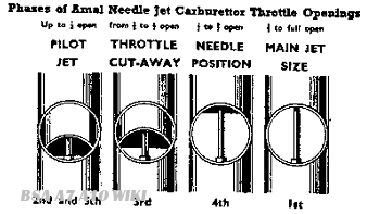
Note: Verify correctness of fuel feed, stop air leaks, check over ignition and valve operation and timing. DECIDE BY TEST WHETHER RICHNESS OR WEAKNESS IS THE TROUBLE AND AT WHAT THROTTLE POSITION. See throttle opening diagrams, Fig. X6.
Procedure
If at a particular throttle opening you partially close the air control, and the engine goes better, weakness is indicated; or on the other hand the running is worse, richness is indicated. THEN YOU PROCEED TO ADJUST THE APPROPRIATE PART AS INDICATED FOR THAT THROTTLE POSITION.
|
Fault at Throttle Positions indicated on Fig. X9
|
||
|
To Cure Richness
|
To Cure Weakness
|
|
|
Fit smaller main jet.
|
1st
|
Fit larger main jet
|
|
Screw out pilot air screw.
|
2nd
|
Screw pilot air screw in.
|
|
Fit a throttle with larger cut-away.
|
3rd
|
Fit a throttle with smaller cut-away.
|
|
Lower needle one or two grooves.
|
4th
|
Raise needle one or two grooves.
|
It is not correct to cure a rich mixture at half throttle by fitting a smaller main jet because the main jet may be correct for power at full throttle: the proper thing to do is to lower the needle.
Information on throttle slides and needle position is given in paragraphs (f) and (e) respectively in the next section entitled TUNING.
Changing from standard petrols to special fuels
Such as alcohol mixtures will, with the same setting in the carburettor, certainly cause weakness of mixture and possible damage from overheating.
Tuning
(a) Figs. X8 and 8a are two diagrammatic sections of the carburettor to show:
1. The throttle stop screw.
2. The pilot air screw.
(b) Throttle stop screw
Set this screw to prop the throttle open sufficiently to keep the engine running when the twist grip is shut off.
(c) Pilot air screw
This screw regulates the strength of the mixture for 'idling' and for the initial opening of the throttle. The screw controls the suction on the pilot petrol jet by metering the amount of air that mixes with the petrol.
Note. The air for the pilot jet may be admitted internally or externally according to one or other of the designs, but there is no difference in tuning.
(d) Main Jet
The main jet controls the petrol supply when the throttle is more than three-quarters open, but at smaller throttle openings although the supply of fuel goes through the main jet, the amount is diminished by the metering effect of the needle in the needle jet.
Each jet is calibrated and numbered so that its exact discharge is known and two jets of the same number are alike.
Never reamer a Jet out, get another of the right size
The bigger the number the bigger the jet. Spare jets ARE SEALED. To get at the main jet, undo the float chamber holding bolt Q (Fig. X4) or Main Jet Cover No. 12 (Fig. X7). The jet is screwed into the needle jet so if the jet is tight, hold the needle jet also carefully with a spanner whilst unscrewing the main jet
(e) Needle and Needle Jet
The needle is attached to the throttle and being tapered either allows more or less petrol to pass through the needle jets as the throttle is opened or closed throughout the range, except when idling or nearly full throttle. The needle jet is of a defined size and is only altered from standard when using alcohol fuels.
The taper needle position in relation to the throttle opening can be set according to the mixture required by fixing it to the throttle with the needle clip spring in a certain groove (see illustration above), thus either raising or lowering it. Raising the needle richens the mixture and lowering it weakens the mixture at throttle openings from quarter to three-quarter open (see illustration. Fig. X9).
(f) Throttle Valve Cut-away
The atmospheric side of the throttle is cut away to influence the depression on the main fuel supply and thus gives a means of tuning between the pilot and needle jet range of throttle opening. The amount of cut-away is recorded by a number marked on the throttle, viz.: 6/3 means throttle type 6 with No. 3 cut-away; larger cut-aways, say 4 and 5, give weaker mixtures, and 2 and 1 richer mixtures.
(g) Air Valve
Is used only for starting and running when cold, and for experimenting with, otherwise run with it wide open.
(h) Tickler
A small plunger located in the float chamber lid. When pressed down on the float the needle valve is pushed off its seat and so 'flooding' is achieved. Flooding temporarily enriches the mixture until the level of the petrol subsides to normal.
Sequence of Tuning
Tune up. In the following order only, by so doing you will not upset good results obtained.
Note. The carburettor is automatic throughout the throttle range—the air control should always be wide open except when used for starting or until the engine has warmed up. We assume normal petrols are used.
Read remarks on Fault Finding and Tuning for each tuning device and get the motor going perfectly on a quiet road with a slight up gradient so that on test the engine is pulling.
1st - Main Jet with throttle in position
Test the engine for full throttle; if when at full throttle, the power seems better with the throttle less than wide open or with the air valve closed slightly the main jet is too small. If the engine runs 'heavily' the main jet is too large. If testing for speed work note the jet size is rich enough to keep engine cool, and to verify this, examine the sparking plug by taking a fast run, declutching and stopping engine quickly. If the plug body at the end has a bright black appearance, the mixture is correct; if sooty, the mixture is rich; or if a dry grey colour, the mixture is too weak and a larger jet is necessary.
2nd - Pilot Jet with throttle in position 2 and 5
With engine idling too fast with the twist grip shut off and the throttle shut down on to the throttle stop screw, and ignition set for best slow running: (1) Loosen stop screw nut and screw down until engine runs slower and begins to falter, then screw the pilot air screw in or out to make engine run regularly and faster. (2) Now gently lower the throttle stop screw until the engine runs slower and just begins to falter, then lock the nut lightly and begin again to adjust the pilot air screw to get best slow running; if this second adjustment makes engine run too fast, go over the job again a third time. Finally, lock up tight the throttle stop screw nut without disturbing the screw's position.
3rd - Throttle Cut-away with throttle in position
If, as you take off from the idling position, there is objectionable spitting from the carburettor, slightly richen the pilot mixture by screwing the air screw in about half a turn, but if this is not effective, screw it back again and fit a throttle with a smaller-cut-away. If the engine jerks under load at this throttle position and there is no spitting, either the throttle needle is much too high or a larger throttle cut-away is required to cure richness.
4th - Needle with throttle in position 4
The needle controls a wide range of throttle opening and also the acceleration. Try the needle in as low a position as possible, viz., with the clip in a groove as near the end as possible; if acceleration is poor and with air valve partially closed the results are better. raise the needle by two grooves; if very much better try lowering needle by one groove and leave it where it is best.
Note. If mixture is still too rich with clip in groove No. 1 nearest the end—the Needle Jet probably wants replacement because of wear. The needle itself never wears out.
5th - Finally go over the idling again for final touches.
CARBURATION AT HIGH ALTITUDES - ALL MODELS
The carburetter settings of all B.S.A. Motor Cycles are designed to give the beat all round performance at altitudes of a few thousand feet.
At greater altitudes the air becomes rarefied with the result that the mixture is incorrect.
To overcome this difficulty it is necessary to reduce the size of the main jet, the reduction depending on the altitude at which the machine is mainly used.
The table below shows the percentage of reduction at given altitudes, but it must be emphasised that while the alteration to jet size will correct the mixture, it will not replace the lost power. This can only be corrected by "Blowing" or super-charging.
It may also be advisable to re-tune the carburetter for smaller throttle openings this should be done in accordance with Service Sheet 706.
|
Altitude.
|
Percentage of reduction in jet size.
|
|
3.000 feet
|
5%
|
|
6.000 feet
|
9%
|
|
9.000 feet
|
13%
|
|
12.000 feet
|
17%
|