

GENERATORS - Models E3H and E3HM
All Models except Dl, C10L, C11G, C12, C15 & B group fitted with alternator
General
The generator is a shunt-wound two pole machine, arranged to work in conjunction with a regulator unit to give an output which is dependent on the state of charge of the battery and the loading of the electrical equipment in use. When the battery is in a low state of charge, the generator gives a high output, whereas if the battery is fully charged the generator gives only a trickle charge to keep the battery in a good condition without overcharging. In addition, an increase of output is given to balance the current taken by the lamps when in use.
Models E3H and E3HM are similar in construction. The former will be found on motor cycles having separate magneto or coil ignition, while Model E3HM is the generator portion of the combined unit known as the "Magdyno".
Routine Maintenance
Lubrication
The lubricator at the commutator end bracket must be given a few drops of good grade thin machine oil every 1,000—2.000 miles. The bearing at the driving end is packed with H.M.P. grease and will last until the machine is taken down for a general overhaul, when the bearing should be repacked.
Inspection of commutator and brush gear
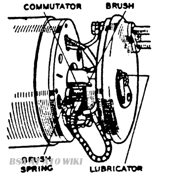
Fig. Y.30. Commutator and bracket assembly
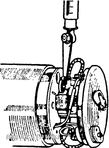
Fig. Y.30. Commutator and bracket assembly
About once every six months remove the cover band for inspection of commutator and brushes. The brushes are held in contact with the commutator by means of springs. Move each brush to see that it is free to slide in its holder; if it sticks, remove it and clean with a cloth moistened with petrol. Care must be taken to replace the brushes in their original positions, otherwise they will not "bed" properly on the commutator. If, after long service, the brushes have become worn to such an extent that the brush flexible is exposed on the running face. or if the brushes do not make good contact with the commutator, they must be replaced by genuine Lucas brushes. The commutator should be free from any trace of oil or dirt and should have a highly polished appearance. Clean a dirty or blackened commutator by pressing a fine dry cloth against it while the engine is slowly turned over by means of the kick starter crank. (It is an advantage to remove the sparking plug before doing this). If the commutator is very dirty, moisten the cloth with petrol.
Test Data
Cutting-in speed: 1250--1500 r.p.m. at 7 generator volts.
Output: 6.5 amps. at 1900—2200 r.p.m. at 7 generator volts, taken on 1.1 ohm resistance load. Resistance to be capable of carrying 10 amps. without overheating. Field resistance 3.2 ohms.
Servicing
Testing in position to locate fault in charging circuit
In the event of a fault in the charging circuit, adopt the following procedure to locate the cause of trouble
Check that the generator and regulator unit are connected correctly. The generator terminal "D" should be connected to the regulator unit terminal "D" and generator terminal "F" to regulator unit terminal "F"
Remove the cables from the generator terminals "D" and "F" and connect the two terminals with a short length of wire. Start the engine and set to run at normal idling speed.
Connect the positive lead of a moving coil voltmeter, calibrated 0 —10 volts, to one of the generator terminals and connect the negative lead to a good earthing point on the generator yoke or engine.
Gradually increase the engine speed, when the voltmeter reading should rise rapidly and without fluctuation. Do not allow the voltmeter reading to rise above 10 volts, and do not race the engine in an attempt to increase the voltage. It is sufficient to run the generator up to a speed of 1.000 r.p.m. If there is no reading, check the brush gear as described below. If there is a low reading of approximately 1/2 volt, the field winding may be at fault. If there is a reading of approximately 11 to 2 volts, the armature winding may be at fault.
Remove the cover band and examine the brushes and commutator. Hold back each of the brush springs and move the brush by pulling gently on its flexible connector. If the movement is sluggish, remove the brush from its holder and case the sides by lightly polishing on a smooth file. Always replace brushes in their original positions. If the brushes are worn so that they do not bear on the commutator, or if the brush flexible is exposed on the running face. new brushes must be fitted.
Test the brush spring tension with a spring scale. The correct tension is 10—15 oz., and new springs must be fitted if the tension is low.
If the commutator is blackened or dirty, clean it by holding a petrol-moistened cloth against it while the engine is turned slowly by means of the kick start (with sparking plug removed).
Re-test the generator as above. If there is still no reading on the voltmeter, there is an internal fault and the complete unit, if a spare is available, should be replaced. Otherwise the unit must be dismantled for internal examination.
If the generator is in good order, restore the original connections. Connect regulator unit terminal "D" to generator terminal *'D" and regulator terminal "F" to generator terminal "F". Proceed to test the regulator unit as described in Service Sheet No. 804.
To Dismantle
Remove the generator from the motor cycle. To remove the generator from the Magdyno. unscrew the hexagon-headed nut from the driving end cover and slacken the two screws securing the band clip. Proceed to dismantle, as follows:
On E3HM machines. Bend back the tag on the washer B Fig. Y.33. locking the screw A securing the driving gear C and remove the screw. On E3H machines, withdraw the cotter pin "A" and remove the nut B from the armature shaft. Withdraw the gear from the shaft by carefully levering it off or by means of an extractor. Remove the key(s) D. from the shaft.
Remove the cover band H. hold back the brush springs and lift the brushes from their holders.
Take out the screw J with spring washer, from the cent re of the black moulded end cap G Draw the cap away from the end bracket, take off terminal nuts F and spring washers, and lift the connections off the terminals.
Unscrew and remove from the driving end bracket the two through bolts L securing the driving end bracket N and commutator end bracket Q to the yoke M. Hold the nuts K at the commutator end while unscrewing the bolts, and take care not to lose the nuts.
On E3HM Machines. Remove the bearing retaining plate P from the driving end bracket secured by two screws and a long threaded bolt. Unscrew the nut R from the end of the armature shaft and the armature can then be removed from the driving end bracket N by means of a hand press.
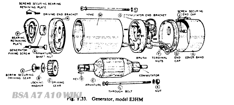
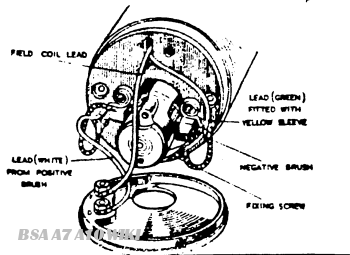
Fig. Y.34. Generator connections Note.—On later machines, the white lead is omitted, the brush flexible lead being connected direct to terminal "D"
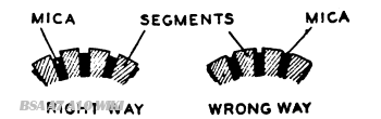
Fig. Y.35 Method of undercutting commutator insulation
On E3H Machines remove the bearing nut T and the oil thrower and washer S. Withdraw the three screws securing the retaining plate P. The armature can then be removed from the driving end bracket N by means of a hand press.
Take out the screw securing the green field coil lead with the yellow sleeve to commutator end bracket and remove the end bracket Q withdrawing the connectors through the slot in the insulating plate
Unscrew the three screws securing the insulating plate to the commutator end bracket and remove the plate complete with brush gear.
Commutator
Examine the commutator. If it is in good condition, it will be smooth and free from pits or burned spots. Clean with a petrol-moistened cloth. If this is ineffective, carefully polish with a strip of very fine glass-paper while rotating the armature. To remedy a badly worn commutator, mount the armature with or without the drive end bracket in a lathe, rotate at high speed and lake a light cut with a very sharp tool Do not remove more metal than is necessary. Polish the commutator with very fine glass-paper.
Undercut the mica insulation between the segments to a depth of 1/32in This value uncertain.. with a hacksaw blade ground down until it is only slightly thicker than the mica,
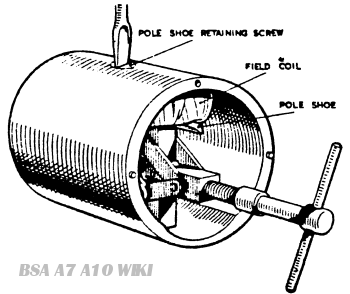
Fig. Y.36. Pole shoe and field coil assembly
Field Coil
Measure the resistance of the field winding by means of an ohm meter. If this is not available, connect a 6-volt D.C. supply with an ammeter in series across the coil. The ammeter reading should be approximately 1.9 amperes. No reading on the ammeter indicates an open circuit in the field winding.
To check for earthed coil, connect a mains test lamp between one end of the coil and the yoke. If the bulb lights, there is an earth between coil and yoke.
In either case, unless a replacement generator is available, the field coil must be replaced. but this should only be attempted if a wheel-operated screwdriver and pole shoe expander are at hand, the latter being especially necessary to ensure that there will not be any air gap between the pole shoe and the inner face of the yoke.
To replace the field coil, proceed as follows:
Unscrew the pole shoe retaining screw (Fig. Y.36) by means of the wheel-operated screwdriver.
Draw the pole shoe and field coil out of the yoke and lift off the coil.
Fit the new field coil over the pole shoe and place it in position inside the yoke. Take care to ensure that the taping of the field coil is not trapped between the pole shoe and the yoke. Locate the pole shoe and field coil by lightly tightening the fixing screw. Insert the pole shoe expander, open to its fullest extent and tighten the screw. Remove the expander and give the screw a final tightening with the wheel-operated screwdriver. Lock the screw in position by caulking, that is, by tapping some of the metal of the yoke into the slot in the head of the screw.
Armature
The testing of the armature winding requires the use of a voltdrop test or a growler. If these are not available, the armature should be checked by substitution. No attempt should be made to machine the armature core or to true a distorted armature shaft.
Bearings
A ball bearing is fitted at the driving end and a plain porous bronze bearing bush at the commutator end.
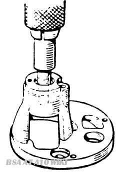
Fig. Y.38. Fitting bearing bush using a shouldered mandrel
Bearings which are worn to such an extent that they will allow side movement of the armature shaft must be replaced. To replace the bearing bush at the commutator end. proceed as follows:
Remove the screw, press the bearing bush out of the commutator end bracket and remove the felt washer. (See Fig. Y.37.)
Press the new bearing bush into the end bracket using a shouldered mandrel (Fig. Y.38) of the same diameter as the shaft which is to fit in the bearing. (Note: Before use. new bearing bushes should be stored in a covered container and fully covered with oil of a grade equivalent to Mobiloil Arctic, or other good thin mineral oil. The minimum time of soaking should normally be 24 hours, but in cases of extreme urgency this period may be shortened by heating the oil to 100°C., when the time of immersion may be reduced to 2 hours). The bush should be pressed in until it is flush with the face of the end bracket. Fit the felt washer in the space between the bearing and the wall of the bearing housing.
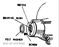
Fig. Y.37. Commutator end bracket with bearing bush
The ball bearing at the driving end is replaced as follows:
Remove bearing retaining plate from driving end bracket as previously described.
Press the bearing out of the end bracket, using a metal drift locating on the inner journal of the bearing (Fig. Y.39).
Wipe out the bearing housing and pack the new bearing with H.M.P. Grease. Position the bearing in its housing and press it squarely home. applying pressure on the outer journal of the bearing (Fig. Y.40).
Reassembly
In the main, the reassembly of the generator is a reversal of the operations described in the paragraph on dismantling, bearing in mind the following points:
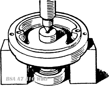
Fig. Y.39. Removing the ball race
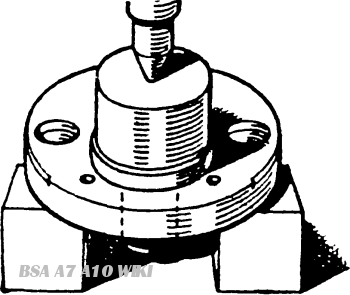
Fig Y.40. Fitting the ball race
The field coil lead fitted with the short length of yellow tubing must be connected together with eyelet of the negative brush to the commutator end bracket by means of the screw provided.
The second field coil lead must be connected to terminal F on the moulded end cap.
The lead (coloured white) from the terminal on the positive brush box must be connected to terminal D on the moulded end cap.
(Note: On later machines, the brush flexible lead is connected direct to terminal D and the white lead is omitted.)
take care to refit cover band in original position and make sure that the securing screw, when of flush-fitting pattern, does not short on brushgear.