
MAGNETO
- A Group Models
These magnetos are of the rotating armature pattern. The magnet is cast into the body, so eliminating joints and improving the weatherproof properties of the magneto. The magnetos also incorporate an automatic timing control.
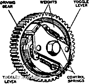
FIg.Y1. Automatic timing control
The automatic timing control (Fig. Y1) employs a driving gear carrying a plate fitted with two pins. A weight is pivoted on each pin and the movement of the weight is controlled by a spring connected between the pivot end of the weight and a toggle lever pivoted at approximately the centre of the weight. Holes are provided in each toggle lever, in which pegs on the underside of a driving plate secured to the magneto spindle are located. This plate is also provided with stops which limit the range of the control. When the magneto is stationary, the weights are in the closed position and the magneto retarded for starting purposes. As the speed is increased, centrifugal force acting on the weights overcomes the restraining influence of the springs and the weights move outwards, causing relative movement to take place between the driving gear and the magneto spindle, so advancing the timing. By careful design of the springs, the characteristics of the control can be arranged to conform more closely with the engine requirements than is the case with other types of control.
ROUTINE MAINTENANCE
Lubrication
To be carried out every 3.000 miles.
The cam is supplied with lubricant from a felt pad contained in a pocket in the contact breaker housing. A small hole in the cam. fitted with a wick, enables the oil to find its way on to the surface of the cam. Remove the contact breaker cover and turn the engine over until the hole in the cam can be clearly seen and then carefully add a few drops of thin machine oil. Do not allow any oil to get on to the contacts. When the magneto is dismantled the felt pad should be removed, soaked in thin machine oil and after removing surplus oil, replaced.
The contact breaker rocker arm pivot also requires lubrication and the complete contact breaker must be removed for this purpose. Take out the hexagon-beaded screw from the centre of the contact breaker and pull the contact breaker off the tapered shaft on which it fits. Then push aside the rocker arm retaining spring, prise the rocker arm off its bearing and lightly smear the bearing with clean engine oil. At the same time, also lightly smear the contact breaker with clean engine oil.
When replacing the contact breaker, take care to ensure that the projecting key. on the tapered portion of the contact breaker base. engages with the keyway cut in the magneto spindle, otherwise the timing of the magneto will be upset. Tighten the hexagon-headed screw with care ; it must not be too slack, nor must undue force be used.
Adjustment
To be carried out every 3.000 miles.
Remove the contact breaker cover and turn the engine until the contacts are fully opened. Check the gap with a gauge having a thickness of .012in. If the setting is correct, the gauge should be a sliding fit, but if the gap varies appreciably from the gauge it should be adjusted. Keep the engine in the position to give maximum opening of the contacts, slacken the locknut and turn the contact screw by its hexagon head until the gap is set to the gauge. Finally tighten the locknut and re-check the setting.
Cleaning
To be carried out every 6,000 miles.
Take off the contact breaker cover and examine the contact breaker. If the contacts are burned or blackened, clean them with fine carborundum stone or with very fine emery cloth, and afterwards wipe away any dust or dirt with a petrol-moistened cloth. Cleaning of the contacts is made easier if the contact breaker is removed. Procedure is given above.
Remove the high tension pickups, wipe clean and polish with a fine dry doth. The high tension pickup brush must move freely in its holder. If it is dirty, clean with a cloth moistened with petrol. If the brush is worn to within 1/8in. of the shoulder it must be renewed. While the high tension pickup is removed, clean the slip ring track and flanges by holding a soft cloth on the ring by means of a suitably shaped piece of wood. while the engine is slowly turned.
Replacement of High Tension Cable
If, on inspection the high tension cable shows signs of perishing or cracking it must be replaced by a suitable length of 7mm. rubber-covered ignition cable.
To fit a new high tension cable to a pick-up terminal, bare the end of the cable for about 1/4in., thread the knurled moulded nut over the cable, thread the bare wire through the washer removed from the end of the old cable and bend back the strands. Finally screw the nut into the pick-up.
SERVICING
Testing Magneto in position on engine
Testing magneto in position to locate cause of misfiring or failure of ignition
Disconnect the cable from one of the sparking plugs and hold it so that the terminal end is about 1/8in. from some part of the cylinder block while the engine is fumed over.
If the spark that jumps from the cable end is strong and regular the fault lies in the sparking plug which must be removed for examination and if necessary cleaned and adjusted or replaced.
Next examine the high tension cable. After long service it may have become cracked or perished and the magneto may be sparking through to a metal part of the engine or frame.
If the magneto has been replaced recently it may be incorrectly timed. Refer to Service Sheet No. 203
If the performance of the magneto is still not satisfactory, the contact breaker may require cleaning or adjustment. If the contacts are badly burned they should be renewed by a replacement contact set. If the contact breaker is in good order, there may be an internal fault in the magneto (see paragraph below).
To Dismantle
First remove the safety gap screw and the earthing brush otherwise the armature and slip ring may be damaged whilst dismantling. The safety gap screw is usually fitted in the underside of the magneto and the earthing brush under the name plate at the contact breaker end.
Remove the high tension pick-ups, secured by spring clips. Take care to retain the gasket fitted under the pick-up for use when reassembling.
Draw the armature out of the magneto body. There is no need to put a keeper across the magnet, as it retains its properties more or less indefinitely. Although it loses a certain immaterial amount of power on the first removal of the armature, subsequent removals do not affect it.
Do not allow the magneto body to come into close contact with any iron filings as they may become attracted to the magnet and cause the armature to bind.
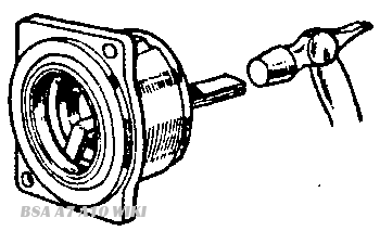
Fig. Y2. Removing outer race
When the armature is removed it should be examined for mechanical faults such as a cracked or bent shaft. Any defect in the winding or condenser needs special equipment to detect, and in the event of trouble being suspected, a complete service armature should be fitted.
It is important that the two ball bearings which support the armature shaft are in good condition. If they are packed on assembly with a suitable high melting point grease they will stand an almost unlimited amount of normal wear. but if they start to fail due to a bent shaft or other cause, they must be replaced. The balls and cages can readily be removed off the inner races which can then be pulled off the armature shaft using an extractor. The outer races can be removed with an expanding collet type extractor or by means of a tool as shown in Fig. Y2.
Carefully examine the slip ring and if it is damaged in any way it must be replaced. To do this take off the inner race of the bearing using an extractor, lift off the shims and the grease flinging plate and pull the slip ring off the shaft. (Note : When removing the inner race the extractor must bear on the brass shaft extension and not on the electric contact or insulator down the centre of the shaft. A disc of appropriate diameter can be placed across the face of the shaft extension). Carefully straighten the wire coming from the armature and see that the bared end is clean, then fit the new slip ring over the shaft, taking care that the wire enters the hole in the boss in the slip ring and that it goes fully home without bending. Seal the lead-in to the slip ring boss with varnish—a special air drying varnish is used at the works but shellac varnish can be used in an emergency.
Replace the grease flinging plate, the full number of shims and inner race of the bearing.
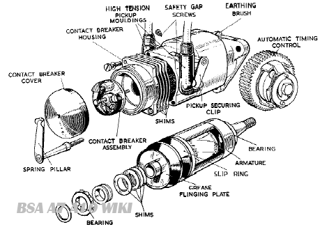
Fig. Y3 The Magneto (exploded view)
Testing
If test apparatus is not available, a rough check of the armature windings can be made by means of a two-volt battery (a tapping across one cell of the motor cycle battery) and an ammeter.
To check the primary winding of the armature
Screw the contact breaker retaining screw into the end of the armature shaft. Connect one terminal of the battery to one terminal of the ammeter. Connect the second terminal of the ammeter to the screw in the armature shaft. Connect the second terminal of the battery to the metal body of the armature.
The ammeter will record the current taken by the armature primary winding and1 should be approximately 4 amperes.
To check the secondary winding of the armature
Leave the connections as detailed for the primary winding check.
Take a piece of high tension cable about 15in. long and bare one end back about 1/2in. and the other end about 4in. Wrap the longer bared end round the brass insert of the slip ring and hold the other end about 1/8in. from the body of the armature.
If the lead from the battery which was connected to the armature body to test the primary winding is then flashed quickly on and off the body a spark should occur between the high tension wire and the armature body.
Failure to spark indicates a fault either in the armature windings or the condenser and a replacement armature must be fitted.
An armature test can be carried out by connecting in series an 8-volt accumulator, a four lobe cam and contact breaker (having 45° closed period) and the armature under test, the contact breaker to coil connection being at earth potential. A 0.2 mfd. condenser must be connected across the contacts. Run the contact breaker at 750 r.p.m. giving 3,000 operations of the contacts per minute, and connect the high tension cable from the coil to either a 3-point spark gap or rotary gap set to 13 kv. Regular sparking should occur under these conditions. Explore the surface of the winding with an earthed pointer— no flashover must occur.
It should be noted that in the above test, sparking will occur, provided that the armature winding is in order, even if the condenser in-built with the armature is open-circuited. Disconnect the 0.2 mfd condenser from the supply circuit above when regular sparking should continue. Failure to do so indicates that the armature condenser is faulty and a replacement armature must be fitted.
If satisfactory performance is not obtained during the above test, measurement should be made of the maximum primary running current. To do this, include also in the above series circuit a moving coil ammeter (of not more than 5 amperes full scale deflection) and a variable resistance of approximately 5 ohms (of adequate current rating for cool running). Connect the H.T. cable from the coil to a 3-point spark gap set to 5.5 mm. or a rotary gap set to 9.5 kv. Run the contact breaker as before, and adjust the variable resistance until occasional missing occurs, that is, when the coil is just failing to spark regularly. Under these conditions, the permissible primary current as read on the ammeter should be not more than 1.2 amperes.
In both the above tests, it is important that the supply voltage be maintained at B volts, that the cam speed be kept constant, and that the winding under test is not subjected to any external magnetic influence (e.g.. it must not be tested on an iron bed-plate).
Reassembly
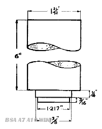
Fig.Y4. Mandrel for replacement of outer races
See that the bearings are clean and if necessary wash them in petrol and dry thoroughly. Lightly pack them with high melting point grease. Fit the inner races on the armature shaft using a hand press and a length of tube fitting over the shaft and locating on the race. Fit the balls and cages in position over the inner races. Place a new oil seal in the bearing housing at the driving end of the magneto body and press the outer races into their housings with a mandrel of the type shown in Fig. Y4, taking care that a suitable serrated insulating washer is positioned between each race and its housing, to ensure that the race is a tight fit in its housing.
See that the slip ring and metal insert are clean ; if necessary carefully wipe it clean with a petrol moistened cloth. See that the inside of the magneto body is clean and free from swarf and insert the armature in the body, drive end first.
Refit the contact breaker end plate taking care that the end plate shims and gasket are in position, and replace and tighten the end plate fixing screws.
Check the armature for end play. It should revolve freely when turned by hand, but no end play should be felt. If necessary adjust by adding or removing shims behind the contact breaker plate until adjustment is correct.
Replace the cam and contact breaker as follows:— First add a few drops of thin machine oil to the felt contained in the contact breaker housing.
Insert the cam in the housing so that the broad slot locates over the two pegs in the contact breaker housing. Fit the contact breaker in position, ensuring that the projecting key on the tapered portion of the contact breaker base engages with the keyway cut in the magneto spindle otherwise the magneto timing will be upset. Tighten the hexagon-headed screw with care; it must not be too slack, nor must undue force be used.
Adjust the contacts to the correct setting and replace the contact breaker cover.
See that the pick-ups are clean and the brushes move freely. Place the cork washers in position on the magneto body, followed by the pick-ups and secure by means of the spring arms.