

RE-ASSEMBLY OF THE ENGINE - A Group Models
The need for cleanliness cannot be over emphasised: all parts should be clean and free from dirt or rust.
The A10 instructions apply to all A7 Models after Engine No. AA7-101.
Smear all bearing surfaces with engine oil.
If the crankshaft has been replaced, the original flywheel, if serviceable, may be retained, and fitted by passing it over the drive side of the crankshaft and bolting to the flange by six high tensile steel bolts. After securely tightening the bolts, they should be peened over on to the nuts to lock them.
The flywheel is positioned with the counter-weight part at the opposite side to the big ends of the cranks. See service sheet No. 712X for balancing.
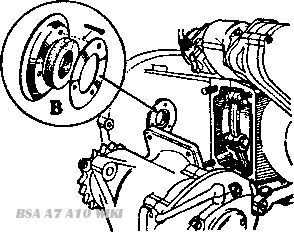
Fig:A16
If the chaincase oil seal is to be renewed, this is effected by placing the actual composition seal Part No. 67-1242, round end outward, into the hole in the crankcase casting extension, and riveting two steel plates, the larger, Part No. 67-1241 inside, and Part No. 67-1243 outside, by three steel rivets. Part No. 67-1244, care being taken not to damage the aluminium case during the riveting operation. (Fig. A.16.)
Having warmed the crankcase halves in a degreasing plant or hot water, insert the steel oil seal washer into the race recess in the drive-side crankcase. Then, by means of an arbor press, insert the race and the blind camshaft phosphor bronze bush. Now press the plain main bearing into the gear-side crankcase. The cases must be suitably supported during these operations to prevent damage.
Press the two camshaft bushes into the case, one from inside and one from outside, and also the idler pinion spindle bush if these parts have been removed.
A phosphor bronze bush is also inserted into the inner cover to carry the outer end of the idler pinion spindle.
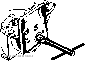
Fig. A.17. The Reaming Jig. Service Tool 61.3275 for A7. 61-3281 for A10 and A7 after eng. AA7-101.
If new camshaft and idler pinion bushes have been fitted it is now necessary to boll the crankcase together and attach the inner cover, then with the aid of Service Tools No. 61-3275 for A7 or 61-3281 for A10 and A7 after AA7-101 use reamer 61-3167 to ream the bushes to .7495/.7485 ins. internal diameter. (Fig. A. 17.) These reaming jigs should also be used to locate the mainshaft reamer if a new mainshaft bush has been fitted. See Service Sheet 711 for details of reamer.
Then unbolt the crankcase and remove the inner timing cover. Remove alt trace of swarf after the reaming operation.
At this point it is advisable to obtain a fixture such as shown in Fig. A. 11 (Chapter 6) and a wooden block with a hole through the centre as shown in Fig. A.15a.
The big end bearing liners should now be placed in the end caps and connecting rods, note that these can only be put in the correct way. because the liners are lipped, but they must, of course, be replaced in their original positions.
When fitting new liners to the A10 it should be noted that each set of four has a small central drill hole. One liner should be fitted in the left hand con rod to line up with the bleed hole which supplements the lubrication of the cylinder bore.
Connect each rod and cap to its crank journal, noting that their numbers correspond, and insert the big end bolts and tighten them. On no account must the castellated nuts be slackened back to allow the insertion of the split pins. If the nut slot does not line up with the hole in the pin when the nut has been fully tightened, the latter must be removed and filed on its flat face until the hole in the pin and nut slot line up.
A torque spanner should be used for tightening these nuts to ensure that they are not over-tightened. Two types of big end bolts have been employed. Early models use 22 T.P.I. B.S.F. bolts and for these the torque spanner should be set at 10 lb. ft. The later type bolt is 26 T.P.I. C.E.I. and a setting of 8 ½ lb. ft. is correct. The later type bolts complete with nut can be used as replacements for the earlier type. From 1956 onwards the torque spanner setting is 22 lbs. ft.
No scraping is necessary with these big end liners and it must not be attempted or damage will result.
Crankshaft end play:
On the A7.When the sprocket is tightened up, the float is taken up. Before tightening, the float should be .005" -.010".
On the A10.On this engine the float is not taken up when tightening the sprocket. The maximum float should be .005'. Any error should be corrected with additional packing shims.
Replace on the drive-shaft of the crankshaft assembly any packing shims which were removed in the dismantling of the engine.
Place this assembly on a thick wooden block through which a hole large enough to take the gear-side main shaft has been bored. Then place the drive-side crankcase half over the drive-shaft and gently tap into position, making sure that the shaft enters the race squarely and goes right home.
Reverse the whole assembly on the block, and then, insert the camshaft into the blind phosphor bronze bush in the drive-side crankcase half. On the A7 place the large twin tappet block with tappets into the recess at the top of the case, so that the oil hole in the block faces towards the gearbox end of the engine, and the opposite side of the block, with slope for securing plate faces the inside of the engine. On the A. 10 the tappets are in the cylinder block.
Smear the joint face of the crankcase with jointing compound, and after it has become tacky, place the gear-side crankcase in position and bolt the crankcases together, making sure that each nut has a shakeproof washer. The two top inside securing bolts have plain locking washers, one side of which is bent over to form a securing tab on the nut.
Insert the two inlet tappet blocks with tappets (A7 only) and before finally tightening the two top inside crankcase securing bolts and the top rear outside bolt, the tappet blocks should be finally lined up by placing a 6 in. steel rule across the milled flats.
When the cases are bolted securely together, the camshaft must rotate freely; otherwise the case alignment is incorrect.
The crankcase breather pipe is a push fit into a hole at the lop of the drive-side case, immediately behind the primary chaincase casting and should be cemented, the lower end being secured by a clip.
Attach the sump plate filter, with the pump suction pipe from the inside of the crankcase passing through the hole in the filter gauze, a paper washer being inserted between the case and plate.

Fig:A19
Now bolt the twin oil tank pipes to the gear-side of the crankcase using jointing compound. and insert the oil release valve unit and rubber washer, if fitted, into its socket (Fig. A.19).
The magneto should now be bolted in position by its three securing bolts, the two short bolts on top and the long bolt underneath the magneto, with a paper washer between the magneto and crankcase.
Timing of the magneto is carried out at a later stage in the assembly, and the magneto drive pinion with its automatic ignition advance device should now be only loosely attached to the magneto spindle.
Place the dynamo in position in its securing carrier on the front of the engine without tightening up. Smear the inner joint face of the inner timing cover with jointing compound, and place the paper joint washer in position on the inner side of the inner cover.
The crankcase breather should now be inserted on to the cam pinion, with a cork washer between the pinion and breather. Smear the breather with engine oil, and place the inner cover in position, securing with the screws. Check end float on the breather and correct if necessary by fitting a thicker cork washer.
Now fit the pistons to the connecting rods, making sure by the marks previously scribed on the inside of each piston, if they are the original ones, that they are in the correct positions.
On the A10 replace the tappets in the reverse order to that for dismantling (see Sheet No. 206).
Place the paper cylinder base washer in position on the top of the crankcase, and rotate engine to bring the connecting rods to top dead centre. Turn the piston rings so that the gaps. which should be .008/.012 in. are not in line with each other. Smear the pistons with engine oil.
Now lower the cylinder block over the pistons, compressing the rings, preferably by the use of Tool No. 61-3061, on the A7 (Tool No. 61-3334 after Engine No. AA7-101), or 61-3262 for the A10, which should be removed when the rings have fully entered the cylinders, and secure the block to the crankcase with the holding down nuts and shakeproof washers.
Replace the four push rods through the tunnel on to their tappets. The two long rods are the inner ones and the two short rods the outer ones.
The magneto should now be timed. To do this, see Sheet No. 203.
Place the chain on the dynamo driven sprocket and the dynamo driving sprocket, which should now be inserted on to the shaft, the concave side of the sprocket inwards, a cork washer being placed between sprocket and case. Fit the nut and a plain washer, turning the edge of the washer on to the nut to lock it after securely tightening.
Adjust the dynamo chain by rotating the dynamo in its cradle to give approx. 1/8 in. to 3/16 in. up and down play on the chain, but not sufficient to foul the inner case retaining screw boss in the centre of the cover, near which the chain passes. Then tighten up the dynamo in its cradle.
The aperture in which the dynamo chain drive runs should now have approx. 1/4lb. of light grease inserted, as no other means of lubrication is provided.
Smear the inner side of the outer cover joint face with jointing compound, place a paper washer on the face when the compound is tacky. Place the cover on to its dowels, and secure with the twelve securing screws, the longest screws at the lower end of the case, and the three shortest screws at the dynamo end of the case.
Next replace the valves into their respective ports, place the springs over the stems and with the top collars in position, and using Service Tool 61-3340 as before, compress the springs until the split collets can be inserted. A dab of grease on the inside of the collets will serve to hold them in position, until the spring is released. Make quite sure that the collets are correctly located.
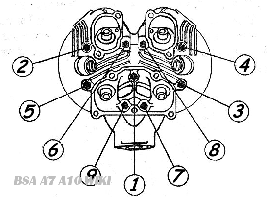
Fig. A20. Tightening order for cylinder head bolts.
Check that the push rods are on their respective tappets, position the cylinder head gasket and then lift the cylinder head into position. Replace the cylinder head bolts. and on the A7 the nuts on the two inverted studs at the rear. Make them all really tight. working diagonally in order to secure even tightness, and leaving the central inclined bolt to the last. When they are all right down give them a final wrench to make certain that they really are tight.
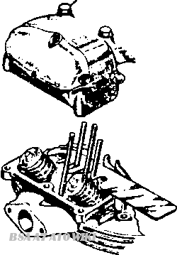
Fig. A21 Push Rod Assembly Tool
Now replace the rocker box or boxes, making sure that the push rods are correctly inserted into the rocker ends, and thoroughly tighten the various nuts and bolts. A special push-rod locating tool Part No. 67-9114 is available which facilitates the location of the push rods while replacing the rocker box of A10 models and A7 after Engine No. AA7-101. The tool should be inserted between the cylinder head and the rocker box from the right hand side. with the shaped edge to the rear and with the outside recesses located by the two rear rocker box holding down bolts, as shown in Fig. A21. The rocker box should then be tightened down and the tool removed just before it is gripped between the rocker box and cylinder head.
Unless care is exercised when replacing the one piece rocker box fitted to the later models it is possible to cause damage to the valve stems. To fit the rocker box, place in position over the valves, and gently ease the four holding down studs through their locating holes in the cylinder head. Check that the rocker box is well clear of the valve spring collars and push it firmly down to its seating on the cylinder head. No force must be used in this operation. After ensuring that the box is firmly seated, fit and tighten the bolts.
Failure to use this method may result in the valve stems being bent, by fouling the rocker box. Although not noticeable in the test run of the engine, this will result in sticking valves and loss of power at high speeds.
Before replacing the rocker box caps or covers, check the tappet clearances
Replace the rocker box connecting links on the A7 and rocker box oil supply pipe.
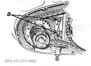
Fig. A22. Chain tensioner securing nuts
Replace the primary chain tensioner and adjuster, locking the securing nuts with a length of wire as in Fig. A.22.
Place the two halves of the clutch thrust plate abutment ring, in position in the groove at the rear of the splined shaft, with a smear of grease to hold them in position.
Slide the clutch thrust washer along the splines over the abutment ring.
Place the clutch centre on a table, rear end upwards, put the clutch chainwheel over the clutch centre, chainwheel upwards, and insert a small quantity of grease into the space between the clutch centre and the chainwheel centre, to hold the eighteen 1/4in. x 1/4in. rollers in position.
Insert the rollers, bring the chain tensioner to its lowest point of adjustment downwards, and then place the duplex chain over the clutch and engine sprockets.
Taking the engine sprocket in the left hand and the clutch chainwheel, including the clutch centre with rollers in the right hand, slide the whole on to the engine and clutch splined shaft at one and the same operation, making sure that no rollers fall from the clutch centre race.
Insert the main shaft locking washer over the splined shaft, with a smear of grease to hold the washer in position. Screw the gearbox mainshaft nut on to the mainshaft, turning the edge of the locking washer over to lock the nut.
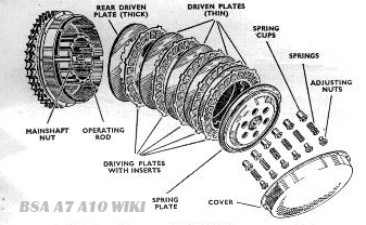
Fig. A23. Cluth assembly exploded view
Slide the clutch plates into the chainwheel housing, rear. driven plate first. (See Fig. A.23).
Fit the spring plate last. and then insert the spring cups and springs into the spring plate, and secure by the six adjusting nuts, screwing these into the spring plate until the collars on the adjusting nuts are flush with the face of the plate.
Place the cush-drive sleeve over the engine shaft, followed by the cush-drive spring over the sleeve, and screw the mainshaft nut on to the engine shaft with a C Spanner, tightening the mainshaft nut up as securely as possible. Put a split cotter pin through the hole in the engine mainshaft, and spread open the split ends.
Adjust the chain by raising the chain tensioner by means of its adjusting screw (C. Fig A22) in the lower part of the chaincase until there is 1/2 in. total up and down movement at the tightest point. Tighten the locknut B and check the adjustment.
Smear the outer primary chaincase jointing edge with jointing compound, allow it to become tacky, place a paper washer on the jointing edge of the cover, and secure in position by means of the twelve cheese-headed screws, noting that these are of varying lengths and must be replaced in their correct positions. Note also that one of the screws is painted red. This serves as an oil level plug and should be located in the screw hole adjacent to the chain tensioner. On earlier models the oil level screw was located in the next hole forward, but the rearward position providing a slightly lower oil level is more suitable. The new position can be obtained on the earlier models by cutting away the rear screw hole on the inside of the outer cover in a similar manner to the existing cutaway. Remove the paint from the original screw and put a dab of red paint on the head of the new drain screw. The screws are of different length and therefore not interchangeable.