COMPLETE DISMANTLING OF THE ENGINE
"A" Group Models (Rigid and Plunger type frames)
The procedure for the dismantling of the engine will be described from the point reached in Chapter 4, when the cylinder head and barrel have been removed.
N0TE: The A10 instructions apply to all A7 models after engine No. AA7 101.
|
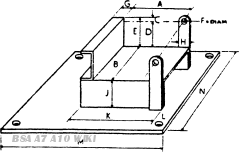
Inches |
mm. |
|
|
A |
43/4- 5” |
120 -125 |
|
B |
31/2” |
85-90 |
|
C |
3/8” |
9 |
|
D |
15/8” |
41 |
|
E |
2” |
50 |
|
F |
7/16” |
11.5 |
|
G |
1 |
25 |
|
H |
3/4" |
20 |
|
J |
2 |
50 |
|
K |
61/4” -61/2” |
155-160 |
|
L |
1 |
25 |
|
M |
12 |
300 |
|
N |
8 |
200 |

Fig. 11 Engine Bench Fixture
Before commencing: to dismantle the engine it will be advantageous to construct a fixture and wooden block such as those illustrated in Figs. A11 and A15(a).
Detach the foot gear change lever from its spindle on the gearbox, and then withdraw the twelve cheese headed screws to allow the removal of the outer timing cover, noting that the lower five screws on the A7 and four on the A10 are the longest screws in the set, and the three at the dynamo end of the cover are the shortest..
A pan should be placed under the engine before the cover is finally removed to hold the waste oil which will fall from the inside of the cover.
Release the dynamo securing strap and turn the dynamo in its housing to allow the tension on the dynamo chain to be relaxed. Remove the large dynamo driving sprocket, that is secured on its taper seat, by a nut and locking washer. After the nut and washer have been removed, a light tap with a hammer on a soft drift placed against the side of the sprocket will loosen it. The sprocket can then be withdrawn together with the chain.
The inner cover is held in position by five screws on the A7 and four on the A10. Take out the screws, remove the cover, and expose the timing gears.
The camshaft gear carries the crankcase breather Part No. 67/130 and a 1/8” thick cork washer between the gear and the breather.
The automatic ignition device may now he removed by releasing its central securing nut. The mechanism is self extracting and as the nut is unscrewed the gear will be pulled from its taper.
Remove the breather Part No. 67/130 if this was not removed at the withdrawal of the inner cover, followed by the circular cork washer in the centre of the pinion.

Fig. A12. Timing Pinion Extractor No 61-3256
The camshaft pinion is keyed and screwed by means of a locknut and washer. Release this nut and washer, and the pinion may be drawn from its shaft in the same manner as the dynamo driving sprocket using Tool No. 61-3256.
Now follows the removal of the idler pinion and its shaft, complete, by pulling away from the crankcase bush with the fingers. The three securing nuts and washers holding the oil pump in position may now be removed. 1'iulo (the locknut and washers from the end of the crankshaft, as the pump is withdrawn, release the hexagon headed worm gear from the crankshaft. Note that both locknut and worm gear are left-hand threaded.
The timing pinion which is keyed to the crankshaft may now be extracted. On all engines after ZA7-1400. AA7-101 and all A10 engines by means of Service Tool 61-3256. Pinions on earlier engines should be removed by the insertion .of a small lever behind the gear, care being taken not to damage the bearing or crankcase during the removal of the pinion.

Fig. A 13 The Oil Pressure Release Valve.
Remove the oil pressure release valve from the crankcase to clean and check it, see Chapter1.
If a composition washer has been inserted into the crankcase below the release valve, a new washer should be used when re-assembling.
Three studs, the one underneath having a long nut, secure the magneto to the crankcase. After the nuts have been removed, the magneto can be pulled from its housing.
Remove the primary chain cover by releasing the twelve securing pins, observing that these are of varying lengths and must be replaced in their correct positions when reassembling. Access to the clutch is gained by the removal of a cover held in position by twelve nuts and bolts. Take care not to damage the oil sealing washer between the cover and the clutch body, when the clutch cover is drawn off.

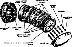
Withdraw the six hexagon headed clutch spring adjusting nuts, together with the springs and cups. The spring plate should now be removed and the clutch mainshaft nut unscrewed after "punching up" the securing washer. Do not remove the clutch plate assembly until the cush drive assembly has been released and removed by taking out the split pin and unscrewing the circular slotted nut on the mainshaft. The two assemblies, with the duplex primary chain, can then be drawn together. Take care that the 18 clutch centre race rollers do not fall out during this operation.
Draw the ground faced clutch thrust plate, Part No. 67-3250, along the splined shaft and remove the two halves of the abutment ring. Part No. 67-3251, from the rear of this plate.
It is now necessary to remove the two securing nuts and the two bolts from the crankcase to release the gearbox. Early A7 models have four bolts.

Fig. A 15. Withdrawing blind camshaft bush (Service Tool No. 61-3159)
Remove the sump plate and filter from the base of the engine, allowing the waste oil to drain into the pan. Do not withdraw the pump suction pipe from the crankcase.
The tappet guide fixing plate can now be removed (A7 only).
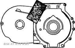
Remove the engine from the bench fixture, and place on a wooden block, drive side downwards. After all the crankcase securing bolts have been slackened, the crankcase halves can be separated. On A7 models it is advisable to leave nuts and washers on one side of the studs between the gearbox flange, as these cannot be replaced after the crankcase has been reassembled.
Gently tap the front and rear of the cases with a soft mallet to part the halves.

Fig. A15(a).
Note the number of shims, if any, on the mainshaft. between the mainshaft bearing and the crankshaft web.
The drive side ball-race on the A7, roller-race on the A10 models, and the gear side white metal bearing, may now be pressed from their respective cases to the inside if in need of attention. It is advisable to warm the crankcase halves in a degreasing plant, or hot water, before attempting to remove the bearings.
Note that there is a steel washer between the drive side race and the case. This acts as an oil seal.
Service Tool No. 61-3159 will withdraw the blind camshaft bush from the drive side crankcase (see Fig. A15).
Tappets and Tappet Guides - removal
The tappet and tappet guides will not normally require attention. If they must be removed, they can be taken out as follows:-

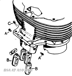
Fig. A15(b).
A7 Models.
The tappets are carried in the crankcase. The exhaust centre double tappet block will fall away when the crankcase halves are separated. The inlet tappet guides may be removed using Service Tool No. 61-3069.
A10 Model & A7 after Engine AA7-101.
The tappets are carried in the cylinder block. Remove the two setscrews "A" (Fig. A15b) and remove the inlet tappets "B." Remove the setscrew "C" taking care not to lose the 3/16in. ball. Push out the retaining pin from the inside of the barrel, and remove the exhaust tappets. Note that the exhaust and inlet tappets are not interchangeable.
Withdrawal of the two securing bolts attaching each of the big end bearing caps to the crankshaft allows the removal of the connecting rods and completes the dismantling of the A7 engine. No useful purpose will be served by attempting to split the actual flywheel assembly, if of the earlier built-up design, because crankshaft grinding can be done in the same way as the normal car engine crankshaft.
The big end bearing liners cannot be replaced in the caps otherwise than in the correct position because these are indented, and fit into their respective slots in the rods and caps.
Dimensions for the regrinding of the crankpins are given in Chapter 7 and must be strictly adhered to. because the bearing liners are manufactured for these dimensions.
The flywheel is bolted to the crankshaft, and should only be disturbed if a new crankshaft has to be fitted. The oilways in the crankshaft should be cleared of any sludge that may have formed. The plugs at each end of the crankshaft may be removed for this purpose.
Thee steel rivets passing through the rear end of the drive side crankcase casting hold the gearbox oil seal in position between two steel plates, and their removal for replacement of the oil seal must be effected with due care, so as not to damage case.
The suction pipe from the sump to the pump on the gear side case must not be disturbed because this is cemented into the case before leaving the works, and a new pipe is supplied as a standard fitting with a new gear side crankcase. This also applies to the small grub screw by the mainshaft plain bearing behind which is situated a ball valve and this must not be disturbed.
There is no need to remove the chain tensioner or adjuster unless a new crankcase is being fitted. After Engine No. AA7-101 the A10 instructions will apply.

