REGULATOR UNIT-Models MCR1 and MCR2
- C10, C11, A, B and M Group Models
This unit houses the generator voltage regulator unit and the cut-out. Although combined structurally, the regulator and cut-out are electrically separate.
On machines fitted with an E3L Dynamo the regulator unit is type MCR2, this unit is slightly different in construction to the MCR1. The procedure for testing and adjusting is, however, unaltered.
Positive Earth Lighting System
Some machines have the battery positive terminal connected to the frame instead of the negative terminal. This does not affect the Regulator Adjustment except that the voltmeter connections should be reversed.
The Regulator
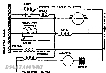
The regulator unit is arranged to work in conjunction with the shunt-wound generator described in Service Sheet No. 809. The regulator is set to maintain a predetermined generator voltage at all speeds, the field strength being controlled by the automatic insertion of a resistance in the generator field circuit, and a current or series winding on the same regulator compensates this voltage figure in accordance with the output current, to ensure that the battery does not receive an excessive charging current when in a discharged condition. Hence the charging current depends upon the difference between the controlled generator voltage and the battery terminal voltage and is therefore at a maximum when the battery is discharged, automatically tapering off to a minimum as the battery becomes charged and its voltage rises. In addition, a form of temperature compensation ensures that the voltage characteristics of the regulator are matched to those of the battery for large variations in working temperature.

Fig. Y.I 5. Circuit diagram of charging system
Normally, during day-time running, when the battery is in good condition, the generator gives only a trickle charge, so that the ammeter reading will seldom exceed 1—2 amperes.
The Cut-Out
The cut-out is an automatic switch which is connected between the dynamo and battery. It consists of a pair of contacts held open by a spring and closed magnetically. When the engine is running fast enough to cause the voltage of the generator to exceed that of the battery, the contacts dose and the battery is charged by the generator. On the other hand, when the speed is low or the engine is stationary, the contacts open, thus disconnecting the generator from the battery and preventing current flowing from the battery through the windings.
Test Data
|
CUTOUT
|
MCR.1
|
MCR.2
|
|
|
Cut-in voltage
|
6.2—6.6 volts
|
6.3-6.7 volts
|
|
|
Drop-off voltage
|
3.5—5.3 volts
|
4.5—5.0 volts
|
|
| Regulator | |||
|
SETTING IN OPEN CIRCUIT
|
|||
|
Reverse current
|
0.7—2.5 amperes
|
3.0—5.0 amperes
|
|
|
10°C.
|
50°F.
|
8.0—8.4 volts
|
7.7—8.1 volts
|
|
20"C.
|
68°F.
|
7.8—8.2 volts
|
7.6—8.0 volts
|
|
30°C.
|
86°F.
|
7.6—8.0 volts
|
7.5—7.9 volts
|
|
40°C.
|
104°F.
|
7.4—7.9 volts
|
7.4—7.8 volts
|
Servicing
Testing In Position To Locate Fault In Charging Circuit
If the procedure given in Service Sheet No. 809 shows the generator to be in order, proceed to check further as follows:—
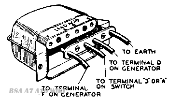
First ensure that the wiring between regulator and battery is in order. To do this, disconnect the wire from the "A" terminal of the regulator (Fig. Y.I 6). It may be necessary in some cases to remove the regulator from the motorcycle.

Fig. Y.16.Connections to regulator unit.
Connect the end of the wire removed to the positive terminal of a voltmeter, and connect the negative voltmeter terminal to an earthing point on the machine
If a voltmeter reading is given, the wiring is in order and the regulator must be examined. If there is no reading. examine the wiring for broken wires or loose connections.
Regulator Adjustment
Remove the cover of the regulator unit, insert a piece of paper between the cut-out contacts, and proceed as follows:
Connect the positive terminal of the moving coil voltmeter (0—10 volts) to the D terminal on the regulator and connect the other lead of the voltmeter to an earthing point on the engine.
Start the engine and slowly increase the speed until the voltmeter needle "flicks2 and then steadies; this should occur at a voltmeter reading between the limits for the particular atmospheric temperature.
If the voltage at which the reading becomes steady is outside these limits, the regulator must be adjusted.
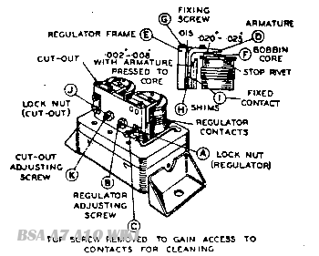
Shut off the engine, release the lockout "A (Fig. Y.17) on the regulator adjusting screw "B" and turn the screw in a clockwise direction to raise the setting, or in an anti-clockwise direction to lower the setting. Turn the screw a fraction of a turn at a time and then tighten the locknut
When adjusting, do not run the engine up to more than half-throttle, as while the dynamo is on open circuit, it will build up to a high voltage if run at a high speed and so false voltmeter reading would be obtained.
Remove paper from between cut-out contacts.
Cleaning the Regulator Contacts
After long periods of service it may be found necessary to clean the vibrating contacts of the regulator. These are accessible if the top screw "C" securing the fixed contact is removed and the bottom screw slackened to permit the fixed contact to be swung outwards. The contacts can then be polished with fine emery cloth.
Mechanical Setting of Regulator

Fig. Y.17. Regulator am) cut-out adjustment and setting.
The armature carrying the moving contact of the regulator is accurately set and should not be removed. If, however, it docs become necessary to re-set the contacts, slacken the two fixing screws "G" Fig. Y.17. and proceed as follows:-—
Insert a .015 in. (0.20 in.) feeler gauge between the back of the armature "D" and the regulator frame "E".
Press back the armature against the frame and down on to the top of the bobbin core with the gauge in position, and lock the armature by tightening the two fixing screws •"G". Check the air gap between the top of the bobbin core "F" and the underside of the armature
"D" (not under the stop rivet). Adjust if necessary to .025 in. (.012" - .020'). by removing shims "H" at the back of the fixed contact on an MCR.1 regulator or by bending the fixed contact bracket on an MCR.2 regulator. The gap between the regulator contacts when the armature is pressed down should now be .002" -.008" (.006" -.017"). Finally check, and if necessary re-set, the electrical adjustment of the regulator.
The figures in brackets refer to the MCR.2 regulator.
Electrical Setting of Cut-out
If the regulator setting is within the correct limits, but the battery is still not receiving. current from the dynamo, the cut-out may be out of adjustment or there may be an open-circuit in the wiring of the cut-out and regulator unit.
Remove the cable from the terminal on the regulator marked A. Remove the voltmeter lead from the D terminal of the regulator unit and connect it to terminal A. Run the engine as before: at a fairly low engine speed, the cut-out should operate, when a voltmeter reading should be given of the same value as that when the voltmeter was connected to terminal D. If there is no reading, the setting of the cut-out may be badly out of adjustment and the contacts not closing.
To check the voltage at which the cut-out operates, the voltmeter must be connected between the D terminal and earth. Start the engine and slowly increase its speed until the cut-out contacts are seen to close, noting the voltage at which this occurs. This should be 6.2—6.6 volts.
If operation of the cut-out is outside these limits, it will be necessary to adjust. To do this slacken the locknut "J" (Fig. Y.I 7) on the cut-out adjustment screw "K" and turn the screw in a clockwise direction to raise the voltage setting or in an anticlockwise direction to reduce the setting, testing after each adjustment by increasing the engine speed until the cut-out is seen to operate, and noting the corresponding reading.
Tighten the locknut after making the adjustment If the cut-out contacts appear burnt or dirty, place a strip of fine glass paper between the contacts then, with the contacts closed by hand, draw the paper through. This should be done two or three times with the rough side towards each contact.
Mechanical Setting of Cut-out
If, for any reason, the armature has to be removed from the cut-out frame, care must be taken to obtain the correct air-gap settings on reassembly. These can be obtained as follows:—
Slacken the two armature fixing screws, adjusting screw "K" and the screw securing the fixed contact Insert a .014" gauge between the back of the armature and the cut-out frame. (The air-gap between the core face and the armature shim should now measure .011"—.015".
• If it does not, fit a new armature assembly). Press the armature back against the gauge and tighten the fixing screws. With the gauge still in position, set the gap between the armature and the stop plate arm to .030"—.034" be carefully bending the arm remove the gauge and tighten the screw securing the fixed contact.
Insert a .025" gauge between the core face and the armature. Press the armature down on to the gauge. The gap between the contacts should now measure .002"— .006" and the drop-off voltage should be between the limits given in the test data. If necessary, adjust the gap by carefully bending the fixed contact bracket.

