REMOVAL OF THE ENGINE GEAR UNIT FROM FRAME
A Group Models (Rigid and Plunger type frames)
It is first necessary to remove the petrol tank. To do this turn off the petrol tap and detach the petrol pipes. If the speedometer is mounted in the tank. disconnect the drive by releasing the strainer bolt under the tank, raising the speedometer clear of the tank and unscrewing the knurled nut connecting the drive to the instrument. At the same time. disconnect the cable for the speedometer light The tank is secured to the frame by a bolt through the steering head lug and another through the seat lug at the rear of the frame top tube. The saddle nose bolt may also be taken out. When these bolts are removed, the tank can be taken off. The tanks on certain models are quickly detach-able and it is only necessary to slacken the nuts to enable the tank to be lifted at the rear end and withdrawn from the frame. In some instances a metal strap beneath the tank joins the two halves and this mast be removed to allow the tank to be withdrawn.
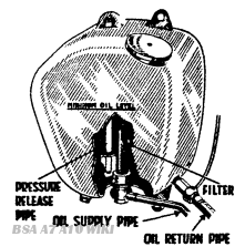
Fig. A8.
left and right hand exhaust pipes and silencers should now be removed. These are secured to the frame by means of a long bolt passing through the front of the crankcase underneath the engine, and at the rear by the pillion footrest securing bolts, the near side nut of which is inside the lower rear chain cover. (Rigid frame models only).
The exhaust pipes are a push fit into the cylinder head, and the finned collars, when fitted, need not be detached.
Remove the carburetter by releasing the two 3/16”. Whitworth bolts from the manifold. The carburetter may then be tied to the rear of the frame out of the way of possible damage during the ensuing work.
Release the two 3/16”. Whitworth nuts on the underside of the front rocker boxes and allow the two steady straps fall away from the engine
It is now necessary to drain the oil from the oil tank, this is accomplished b) unscrewing the 5/16”. Whitworth hexagon-headed plug at the rear corner of the tank or by unscrewing the supply pipe banjo union when no drain plug is fitted (Fig, A8).
When the oil tank is empty, remove the two oil pipe unions secured to the underside of the oil tank, using the B.S.A. combination spanner from the tool kit. Observe that the rear joint houses the oil filter unit, and take care to avoid damaging this component during removal.
The front pipe union also secures the O.H.V. rocker oil supply pipe, and this may be left attached to the engine
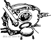
Fig. A9.
Release the rear chain spring link and rotate the wheel to remove the chain from the gearbox sprocket Now remove the remaining front engine securing bolt This bolt passes through the dynamo cover, and the frame distance piece, which will fall away when the bolt is removed (A. Fig. A10).
The dynamo cover is secured to the engine by three bolts B (Fig. A10), which must now be removed, noting that three plain washers are situated between the engine crankcase and the dynamo cover, left hand side only, one on each bolt. These must be replaced on reassembly.
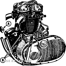
Fig. A10.
The rear of the power unit assembly is secured to the frame by three further bolts, two underneath the gearbox and one behind the magneto. A bolt at the rear of the primary chaincase casting, by the magneto, holds the front of the chainguard, which together with the bolt passing through a bracket on the lifting stay, must be released, and the chainguard drawn away towards the rear wheel
The nut on the central rear cheese-headed primary chain cover screw should be released, allowing the bottom chainguard (rigid frame models) and the oil tank breather pipe dip to become free from the engine unit.
It will be observed that the engine unit is now entirely free from the frame except for the speedometer cable and the clutch cable on top of the gearbox. Push the clutch lever towards the centre of the machine, allowing the inner cable nipple to be removed from the arm, and screw back the cable adjuster on the gearbox to release he outer cable from the unit (Fig. A9).
It is now advisable to obtain the help of an assistant who should place a lever, such as a 12 in. tyre lever, under the front of the unit between the frame and crankcase. Depression of the lever will cause the engine unit to pass over the lower frame tubes to the offside, at which point the engine should be steadied, before removing to a substantial wooden box set on this side of the machine.
Now lift the power unit complete on to the wooden box, crankcase downwards, taking care that the unit does not fall over.